Electrical
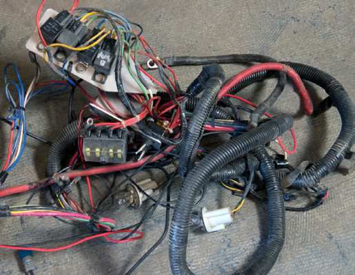
Once the seats were removed during disassembly, the mess of wires started to emerge. The old harness was just a hodgepodge of different wiring. It probably started life as a decent (for the era) wiring harness, but had become a mess as new components were added and temporary fixes became permanent repairs. It wasn’t pretty, but it had been working great. Big Red had recently gone 251.8 mph without a problem…at least not wiring related. There’s an old saying that goes something like, “You can be a novice at a lot of things, but it’s better to be an expert in a couple of things.” The Big Red crew worked under this rule. When it came to wiring, they called a professional. There was a lot of work and money going into the rebuild, so they decided to do Big Red justice and raise the bar on the electrical system. They called Jack Nickerson of Jax Motorsports.
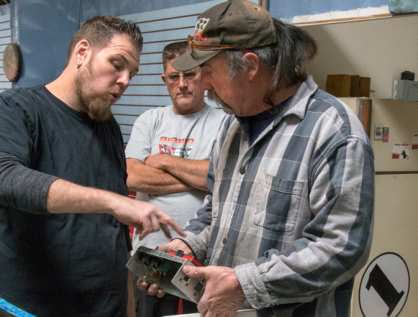
Jack has been building and wiring hot rods, boats, and race cars for over 20 years, and has built quite a reputation as being easy to work with, doing amazing work, and going above and beyond for his customers. It also helped that he was able to work around the shop’s schedule, and work closely with them as the project progressed. Jack took the locations of all the components and built a mock-up
harness out of tubing. This gave him a good idea of how the harness should be routed before laying out a bunch of wires. He showed RJ an example of his work on a harness and bulkhead connector. Every connection will be sealed and protected with abrasion- and fuel-resistant mil-spec heat shrink tubing and heat shrink boots. The guys worked together to lay out the components in module boxes designed and built by Jack to neatly contain components while still being serviceable.
The new rear power distribution module is located in the trunk to the right of the fuel cell. Jack designed and fabricated the box to house the Bussmann power-distribution module, fuel relays, circuit breakers, override test switches, and taillight wiring. The relays and circuit breakers in this box supply power to the transmission fan and either the fuel pumps or the water cooling pumps, depending on whether the car is in Road Race or Land Speed/Top Speed mode. This box was designed so they could switch back and forth between the two by simply plugging or unplugging the trans fan connector and switching out the sub harness that goes to the fuel pumps or water pumps. The box contains and protects the wiring connections.
The main fuse and relay center was designed and completely wired by Jack. Dave built the box out of aluminum and welded it for Jack. It utilizes the same Bussmann power-distribution module to house the relays and circuit breakers for the bulk of the electrical system: ignition, Holley Dominator EFI, cooling, lighting, data acquisition, etc. Jack built the harness that runs along the firewall. It plugs to the main panel (to be located in the glovebox) and contains the main switch panel, brake switch, tach, firewall-mounted starter switch, and more on the driver’s side, while the other side has the other starter switch and other leads for the passenger side.
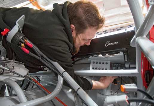
The relay and fuse center is compact, which makes it easy for the team to troubleshoot any problems in the future. Jack didn’t want to have circuit breakers and relays spread all around the car. Having a central location for the bulk of the components makes it easier to perform the first diagnostic check for an electrical failure…checking the circuit breakers. Jack built it as compact as possible to make the circuit breakers and relays easily accessible (and hidden) behind the glovebox
door. It’s good that Jack was able to wire the whole relay and fuse center module outside the car, because working inside the car around the cage and other components was like taking a yoga class for magicians.
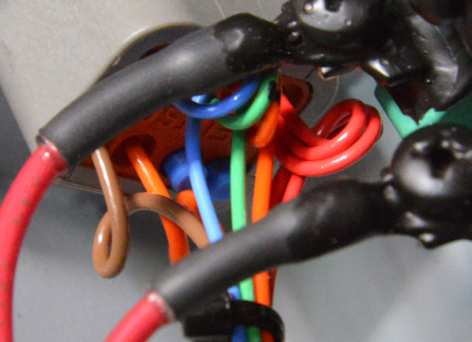
Jack added an additional side plate to the module to house a single 12-volt positive stud for extra ring terminals for additional circuits and two 12-pin Deutsch connectors, which connect the power-distribution panel to the Holley Dominator ECU, ignition system, traction control and Racepak G2X Pro Logger. The power stud is a clean and efficient way to connect battery power to the power-distribution panel. When Jack mounts multiple circuit breakers in a row, he makes a single, copper busbar that connects across multiple positive terminals; in the case of this unit, he made a busbar for the top five fuses and another for the bottom five. This allowed him to run a single, large-gauge 12-volt positive wire to feed five circuit breakers rather than five separate smaller-gauge positive wires. The curls in the wiring near the connector are called “service loops.” They are added to the wires right before they enter the connector. They give extra length to the wire to ease future service of the terminals, as well as provide strain relief for Deutsch connectors. Jack
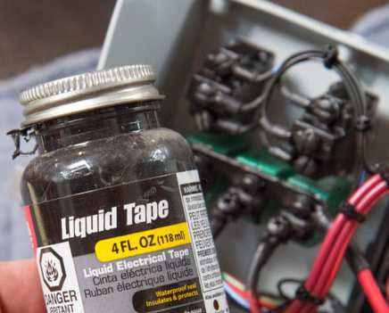
brushed a thin coat of Liquid Tape (brush-on electrical tape) on all the exposed screws, terminals, and busbars. This protects against corrosion and arcing tools across bare terminals, plus it gives extra protection against the screws vibrating loose.
The round, mil-spec Deutsch connector strategically was placed to the side of the module so it’s accessible if the glovebox door is open, just in case they needed to work on the circuits in that connector. The top and bottom flanges
of the module have Dzus fasteners to solidly mount it to the Camaro’s factory dashboard.